As stated in the introduction, MARV has both under water and dry land behaviors. As such an actuation method for both terrains is necessary. A continuous track method is used above ground and a propeller propulsion method is used underwater.
Continuous track works by keeping as large of a flat surface continually on the ground as possible. An example of a configuration used is located to the left. For the purpose of MARV it was decided that the continuous track would make it easier to get out of the water due to the higher amount of surface area on the ramp. The continuous track for MARV is driven by two DC motors at 6V. The motor drivers are Dual 1A TB6612FNG drivers purchased from Sparkfun. The motors will be situated to handle PWM and will rotate in both directions.
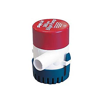
Underwater motion will be controlled by propellers. They will be driven by DC motors hacked from Rule 360 Bilge Pumps. The bilge encasing is cut off leaving the waterproofed motor encasing.  The impellor is then replaced by a propeller. They will be driven by darlington pair transistor setup for one directional thrust. There will be forward thrusters and upward thrusters as I've decided on slightly negative of neutral buoyancy being the best case for this project. If this setup is not sufficient to provide for underwater turning and maneuvering than adjustments will be made to this setup at that time.
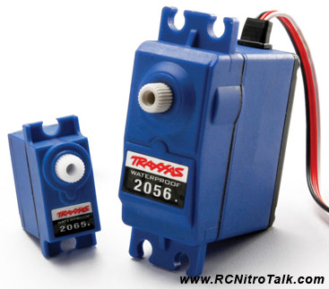
Originally 2056/2065 waterproof servos were going to be used for this task but it was discovered (rather late) that these didn't have high enough RPM to push the servos through the water. This should have been apparent from the beginning, but I didn't think of it till somewhat recently. The RPM of the servos in continuous mode is around 50RPM or perhaps even less. Nothing less than 250RPM give or take would be sufficient for this task.
The hack for the 2056 motors consists of removing the top of the potentiometer and cutting out the limiting tab. For the 2065 motor, it is slightly more complicated as the potentiometer is part of the gear mount mechanism. But using a dremel I can bore out the gear slightly so that it slides around the outside of the potentiometer without rotating it. By supplying a 1.5ms signal the servo can then be adjusted until rotation ceases so that 1.5ms will be neutral on the continuous motion servo. This works for both servos. 1.75ms will provide full tilt right, while 1.25ms will provide full-tilt left. As mentioned these servos appear not to be useful to this project but its worth mentioning the research I've done on them. In addition when controlling direction these servos are +/- 45 degrees rotation servos and go from left 45 degrees to right 45 degrees by the same method mentioned above for the continuous motion.
Below are some pictures of MARV with his Forward/Backward underwater thruster's attached:
Next in line for MARV is to have his up/down motors attached. They will go directly in front of the bilge pumps you see in the picture above. Underneath the battery encasing (the large PVC tube on the top) are two conduit boxes. The smaller conduit box in the front will house the motor drivers, which are simple darlington pair transistors capable of driving 5 amps. These are used since the motors are expected to drive about 1amp continuously with spikes in the 2amp range. Originally the same Sparkfun motor drivers used for the tank drive were going to be used to allow for different speeds and reversible motion, but it was decided it wasn't neccessary and the motor drivers are apt to stop working due to overheating with the large current. This is already somewhat of a problem with the tank drive, but given the small amount of time the tank tread will be on that it is an acceptible occurance.