Facilities
Supersonic combustion tunnel
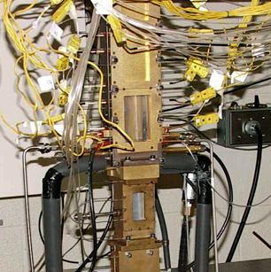
The scramjet wind tunnel facility is capable of testing combustion of hydrogen and hydrocabon fuels at Mach numbers ranging from 1.34 to 3.59. The 1x1 inch (2.5x2.5 cm) cross section testsection is instrumented with pressure ports and thermocouples and may be fitted with quartz windows for visualization and laser-based diagnostics. Different injection schemes may be utilized as well as a fuel pre-heater to investigate the mixing and combustion effect of different parameters. The tunnel has a vitiated air heater burning hydrogen to achieve stagnation temperatures of representative scramjet flight conditions. Fed from the department air compressors, stagnation pressures up to 200 psia (1.4 MPa) can be maintained continously. The combustion tunnel is used for studying supersonic mixing and combustion.
High-pressure combustion chamber
This 1x1 inch (2.5x2.5 cm) cross section test chamber is used for studying hydrogen-oxygen and hydrogen-air combustion at elevated (up to 900 psi/6 MPa) pressures for rocket-engine applications. Through the use of optical diagnostics - primarily LIF - the mixing and combustion of the fuel and oxidizer can be studied through non-intrusive measurements of several minor species, e g OH. Currently, hydrogen-oxygen combustion under moderate to high pressure is being studied in this facility.
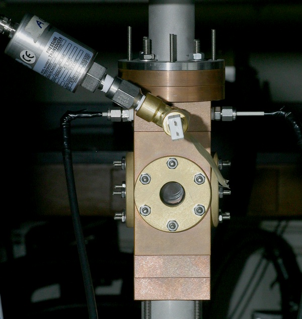
There is also a short AVI movie (25MB) of hydrogen-oxygen combustion at 100 psia (0.7MPa) here. In the future a combination of filtered Rayleigh scattering and OH-PLIF will be applied to the chamber to give simultaneous 2D velocity and OH concentration measurements for CFD model validation.
Liquid jet breakup chamber
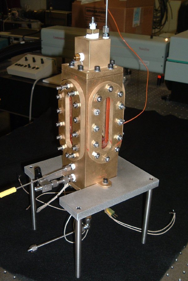
The purpose of this facility is to study liquid jet breakup and evaporation under high temperatures and pressures. The test chamber is 9 inch (230 mm) long and has a 1.8x1.8 inch (46x46 mm) inner cross-section. Optical access is provided through four symmetrically located, 3.3x0.86 inch (84x22 mm) fused silica windows. The chamber can be pressurized (up to 1470 psi/10MPa) and the injected liquid fuel and gases pre-heated independently (up to 400 C). This facility has been used for studying the supercritical behavior of JP-10 and dodecane sprays and is now used to study the breakup of a round fluoroketone jet, simulating cryogenic fuel behavior under high pressure.
Catalytic combustor
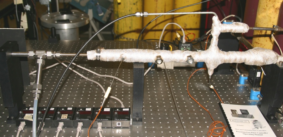
This facility consists of two concentric tubes where the outer surface of the inner tube is covered with a catalyst. The inner tube contains a cooling air flow while the annular region contains a fuel-air mixture that reacts on the catalytic surface. The inner and outer air flows can be independently controlled by a number of massflow controllers from Alicat, allowing equivalence ratios and fuel composition to be varied over a wide range. The incoming air streams can also be preheated through passing through two independently controlled electric heaters, allowing the conditions in a RQL low-NOx gas turbine pre-combustor to be modeled. Measurements are carried out using mass spectrometry of gas samples drawn from above the catalyst surface and through laser-based diagnostics through the fused-silica windows of the testsection. Currently, the catalytic reactions of methane and syngas under atmospheric pressure are studied.
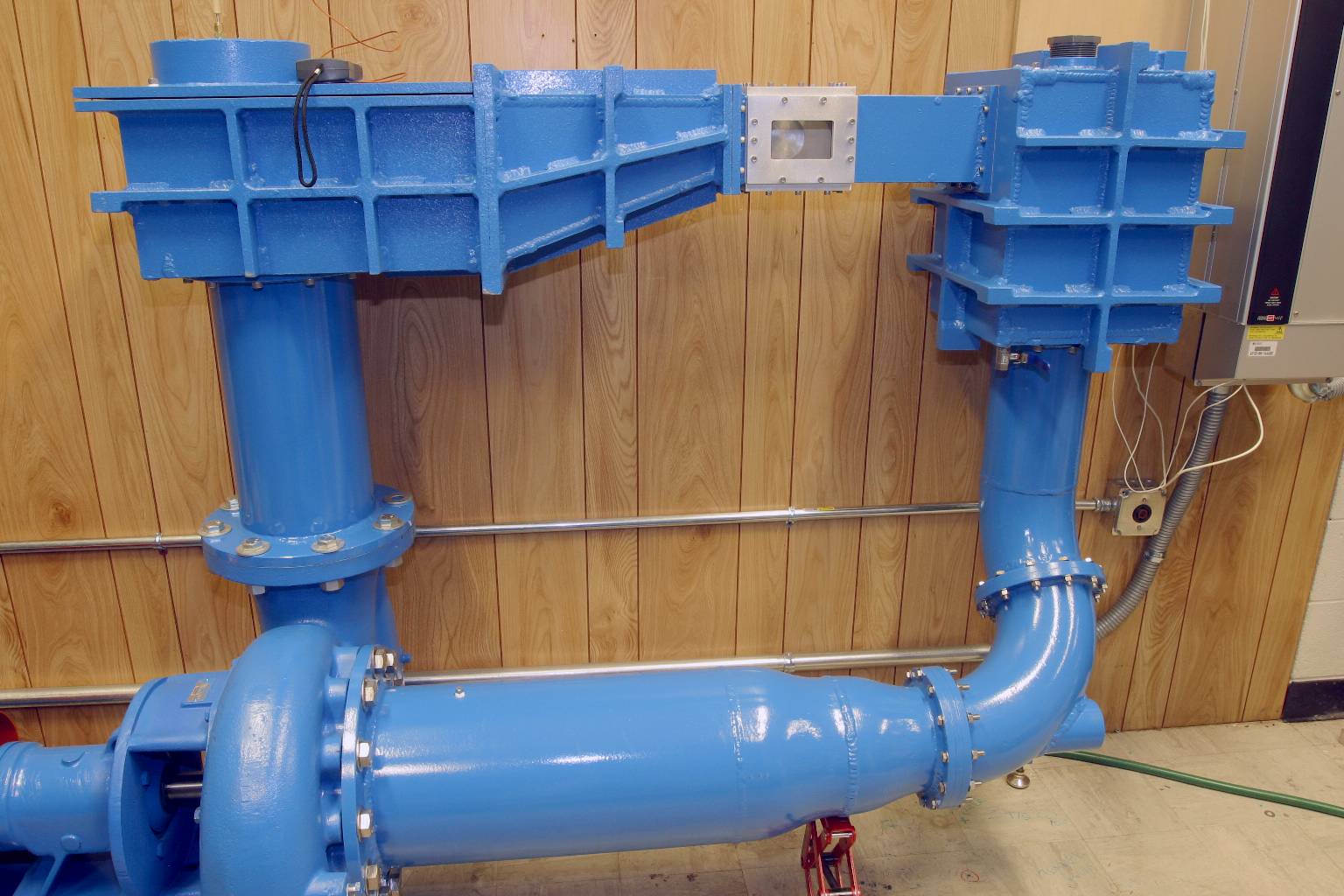
Watertunnel
This new addition to the lab is a watertunnel capable of reaching a speed of 33 fps (10 m/s) in its 4x4 inch (0.1x0.1 m) crossection testsection, enabling high-Re tests on hydrofoils under fifferent angles of attack. Currently the facility is filled with a volatile fluoroketone for studying cavitation under near-critical conditions. The tunnel is driven by a variable-speed 25 hp pump and is fitted with large windows facilitating the application of optical diagnostics, primarily PLIF. With a dedicated pulsed Nd:YLF laser and a rotating-mirror image acquisition system, frame rates of 100- 10,000 Hz are possible. The tunnel is constructed of aluminum and may be vacuumd or pressurized up to 5 bar (75 psia) and is also fitted with a 7.5kW heater, facilitating the investigation of both pressure and temperature effects.
More
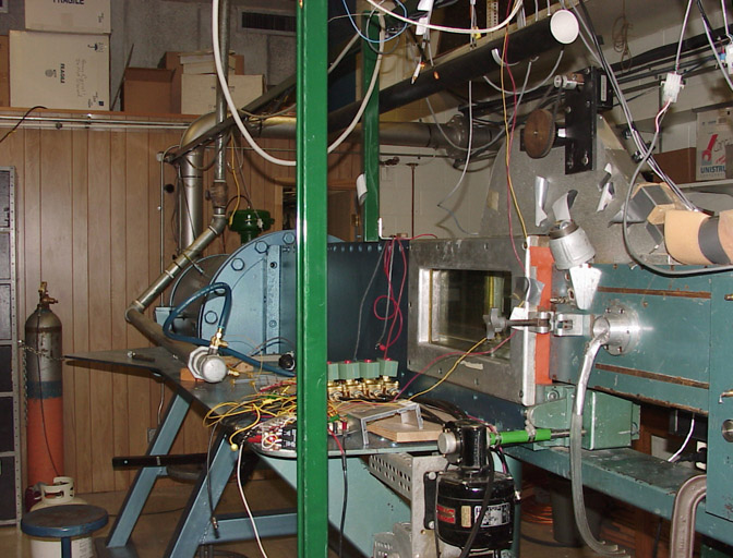
Mach 4 windtunnel
The MAE department Mach 1.5-4 wind tunnel has a 6x6 inch (15x15 cm) testsection equipped with a sting with variable angle-of-attack as well as a Schlieren setup, a PSI9010 pressure scanner and numerous pressure transducers. Using the air storage tanks and high-pressure single-stage screw compressors, 30 s runs can be carried out approximately every 20 minutes at Mach 2. The supersonic wind tunnel was most recently used for tests of inlet instabilities in pulse detonation engines.
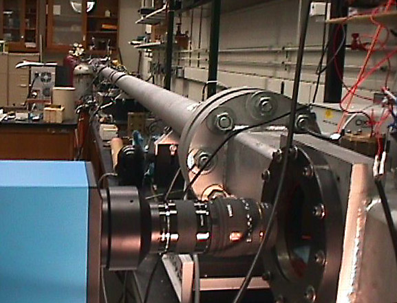
Mach 5 shock tube
The 4 inch (10 cm) diameter double-diaphragm shock tube generates shocks of up to Mach 5 strength. Two test sections are available at the end of the 6 m driven section. The combustion test section, separated by a thin mylar diaphragm from the driven section, is used to measure ignition delay times of premixed gases in the range of 800-2400 K using the reflected shock. CH and OH emissions can be detected by a Hamamatsu R374 photomultiplier using the appropriate narrowband filters. The second test section has a square cross section with optical access and is used for studying shock-droplet interactions and ignition using high-speed cameras.
Back to the Combustion Lab homepage.