Lovely folks from MathWorks.
Lovely folks from MathWorks.
Vision HDL Toolbox™ (VHT) provides pixel-streaming algorithms for the design and implementation of vision systems on FPGAs and ASICs. It provides a design framework that supports a diverse set of interface types, frame sizes, and frame rates, including 1080p high-definition video. The image processing, video, and computer vision algorithms in the toolbox use an architecture appropriate for HDL implementations.
The toolbox algorithms are designed to generate readable, synthesizable code in VHDL and Verilog (with HDL Coder™). The generated HDL code can process 1080p60 in real time.
Detailed below is a typical Simulink® to HDL workflow. Although not shown here, equivalent MATLAB® to HDL workflow is also supported.
It is a good practice to develop a behavioral system using Computer Vision System Toolbox™ (CVST) blocks that process full image frames before moving forward to working on an FPGA-targeting design. Such a behavioral model helps verify the video processing design. Later on in step 2, it can serve as a reference for verifying the implementation of the algorithm targeted to an FPGA.
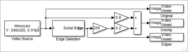
Consider a design that detects and highlights object edges in a video stream. The following diagram shows the structure of a full-frame behavioral model.
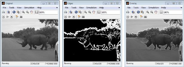
One frame of the source video, the edge detection result, and the overlaid image are shown from left to right in the diagram below.
Note that in this step, VHT has not been in the picture yet.
CVST product models at a high level of abstraction.
The blocks and objects perform full-frame processing, operating on one image frame at a time. VHT blocks perform pixel-stream processing, operating on one image pixel at a time.
Based on the full-frame behavioral model created in step 1, we move forward to developing a parallel FPGA-targeting branch that processes pixel stream. This is when VHT kicks in.
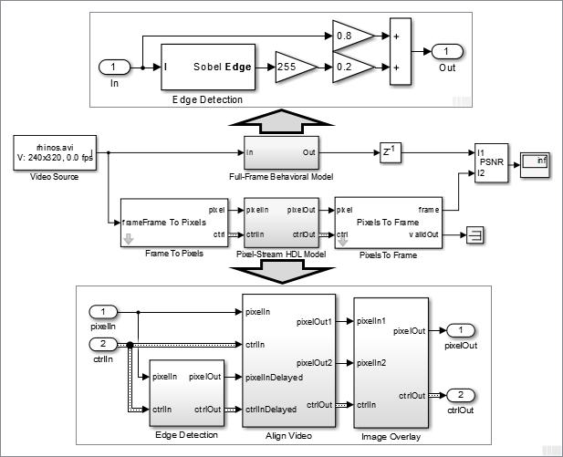
Use Frame To Pixels and Pixels To Frame blocks to convert between full-frame and pixel-stream domains. Due to the nature of pixel-stream processing, unlike the Edge Detection block in the Full-Frame Behavioral Model, the Edge Detector block from VHT inside Pixel-Stream HDL Model/Edge Detection will introduce latency. The latency prevents us from directly weighting and adding two images to obtain the overlaid image. To address this issue, the Align Video subsystem is used to synchronize the two pixel streams before the sum.
While building the streaming portion of the design, the PSNR block continuously verifies results against the original full-frame design. The Unit Delay block between Full-Frame Behavioral Model and PSNR on the top level of the model time-aligns the 2-D matrices for a fair comparison. During the course of the simulation, the PSNR block should give inf output, indicating that the output image from the Full-Frame Behavioral Model matches the image generated from the stream processing Pixel-Stream HDL Model.
VHT sees to it that the stream-based implementations of commonly used video processing algorithms (edge detector, median filter, image filter, etc) are numerically equivalent to their full-frame CVST counterparts. On top of that, VHT also provides HDL support. For example in the model shown in step 2, HDL code can be automatically generated from the Pixel-Stream HDL Model subsystem.
To verify that the generated HDL code is bit-true, cycle-accurate, and synthesizable, use FIL (FPGA-in-the-Loop) simulation.
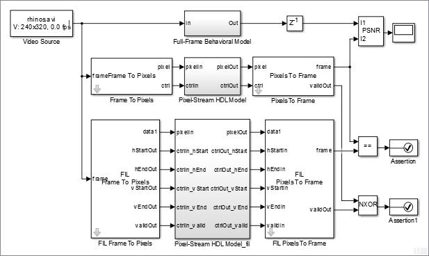
As shown in the model shown above, the FIL workflow generates the Pixel-Stream HDL Model_fil subsystem that runs the HDL code on FPGA.
We can see that our design has been characterized by three different representations (this always reminds me of the Rosetta Stone), namely, a full-frame model, a pixel-stream model, and HDL code, corresponding to the three branches from top to bottom.
The full-frame model sketches your design ideas. VHT (and HDL Coder) guarantees that the HDL code generated from the pixel-stream design is bit-true, cycle-accurate, and synthesizable. The last missing piece is to design a pixel-stream model that it is numerically equivalent to a given full-frame model (see step 2). This is the most challenging part in the workflow.
Last but not least, the generated HDL code can process 1080p HD video in real-time on FPGA.
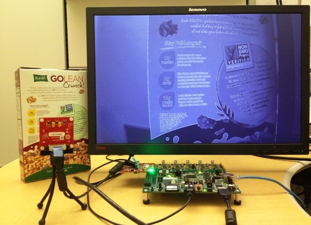
Although a small 240p video source is used in simulation and FIL (steps 1-3) for the sake of simulation speed, the model shown in step 2 has been configured in a way that the model itself, along with the HDL code generated from the Pixel-Stream HDL Model subsystem, works with all standard video formats up to 1080p. This suggests that we only need to maintain one model. Using the same model, Simulink works on small frames like 240p, and the generated HDL code can process 1080p video source.