Setting up a Rayleigh Scattering Experiment
Filtered Rayleigh scattering is a technique which is based on the frequency shift of light that is caused when it is reflected off particles, molecules or atoms that are travelling at a substantial speed in a direction not perpendicular to that of the incident light. Using a very narrow-bandwidth filter (typically Iodine vapor), a large variation in absorption can be achieved even for the small change in frequency caused by the small, relative too the speed of light, velocities typically encountered in laboratory flows. The unfiltered and filtered light that is reflected from the flow is captured on a CCD camera and when the effect of the filtering is evaluated, the velocity of the flow in one direction can be determined given the absorption profile of the filter employed. A large number of parameters need to be considered when choosing and arranging the components of a measurement system for Rayleigh scattering, depending on the flow to be studied. These parameters and the setup chosen in the present experiment will be briefly discussed in this document.
The light source used for Rayleigh scattering is frequently an injection-seeded, pulsed Nd:YAG laser. This is both because of its high power, the narrow bandwidth light produced and because its frequency-doubled wavelength, 532 nm, very closely matches a well-known and efficient absorption range in molecular Iodine. Some investigators have however used a higher harmonic of the 1064 nm light to achieve better signal-to-noise ratios due to the larger Rayleigh crossection at shorter wavelengths and the lower reflectivity of metallic surfaces observed in the UV. Another possible laser choice is the Argon ion laser.
Power
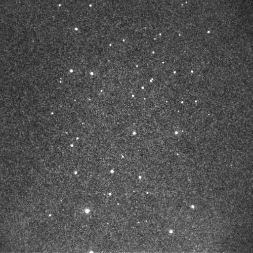
The required power of the light source used will depend on many factors, most importantly the sensitivity of the CCD camera used, the filter characteristics, the size of the area to be illuminated and whether seeding is used or not, but it will generally need to be rather high. Typically a pulse energy of the order of 500 mJ is used for an illuminated area of about 1x1 inch, but for seeded flow (water vapor frequently occurs naturally in high-speed, unheated air-flows) a significantly lower light level can be acceptable. Accidental seeding may however also easily drown any Rayleigh signal, as the below image shows.
Image of M=1.55 jet going upwards in the image showing contamination by dust particles.
Narrow linewidth
Since the flow velocities to be observed are much smaller than the speed of light, the observed Doppler shift will also be very small. Typically, a frequency shift of about 2 MHz per 1 m/s flow velocity will be produced, which can be compared to a laser frequency of 5.6.1014 Hz at 532 nm. Hence, a bandwidth of the order of 100 MHz must be achieved if measurements of reasonable (a few percent) precision are to be achieved. Since the natural bandwidth of a Nd:YAG laser is roughly 30 GHz, a much cleaner light must be produced. To achieve this, the Nd:YAG laser is injection seeded, which means that the laser pulse is initiated by a separate, very narrow-bandwidth seeder laser that stimulates the Nd:YAG laser to emit only light matching that of the seeder laser, giving a bandwidth of 90 MHz. It is also essential that the light emitted stay fixed in wavelength between different pulses, or at least that the frequency of each individual pulse can be measured, because this is what determines the transmission of the iodine filter. Furthermore, it is desirable that the laser can be tuned in frequency to the edge of an iodine absorption band. Our GCR-150 has a 6350 seeder that can be tuned over about 60 GHz.
The filter most frequently used for Rayleigh scattering is a low-pressure (a few torr) molecular iodine filter. The iodine vapor is kept in a cylinder with transparent end plates through which a picture of the flow to be studied is taken. The cylinder is vacuumed and a few iodine crystals are placed in a side arm of the cylinder, which thereafter can be sealed. Much more information about the absorption characteristics of iodine cells can be found in Forkey et al, 1997 (Forkey, J N, Lempert, W R, Miles, R B, "Corrected and calibrated I2 absorption model at frequency-doubled Nd:YAG laser wavelengths", Applied Optics, 36 (27), 1997). The iodine cells are commercially available from
ISSI.Temperature
Through regulating the temperature of the side arm, the amount of iodine vapor and hence its pressure can be controlled. The cell body itself is heated to a higher temperature than the arm so that any vapor that condenses does so in the side arm. The absorption coefficient of the cell increases with the side arm temperature and the absorption peak side slopes grow less steep as the temperature increases. Typical side arm temperatures are in the 30-50oC range and the deepest absorption peaks have transmission coefficients of 3.10-7 for a 10" cell at 40oC. However, it must be remembered that this transmission level is only achieved for truly monocromatic light - even small spurious light produced due to secondary laser modes or the flash bulbs may significantly reduce the realized contrast level(see Seasholz and Buggele, 1997).
Pressure
The partial pressure of iodine at commonly used cell temperatures is very low - typically a few torr. However, some iodine cells are not sealed, but allow the user to supply a gas such as nitrogen to the cell and thereby increase the flexibility of the cell. An increase in pressure causes a somewhat different smoothening of the absorption spectrum than does the thermal broadening. This can be used to create a cell with a linear response over the velocity interval of interest in a specific test.
The CCD camera used must have a high enough resolution to capture the flow structures of interest, but need also be very light sensitive because of the low level of reflected light, especially for unseeded flow. The data transfer rate and exposure time of the camera is normally not critical since these parameters are chiefly determined by the repetition rate and pulse length of the laser, respectively. For the present experiment, a CCD camera with a resolution of 512x512 pixels and a data transfer rate of roughly 10 images per second has been chosen. The camera is also equipped with a photo multiplier that can be used to amplify the incoming light.
I also have a pdf document about
Rayleigh scattering I wrote as a term paper for EGM6813, as well as a term paper written for a class in Statistical Thermodyamics (CHM6461) about the velocity distribution of air molecules and the impact this has on the scattered light.While this work is still on-going, the state of the project in Aug 2003 is summarized in this (PDF) FLUCOME '03 paper. Future development includes incorporating a second I-CCD camera to be able to study unsteady flow phenomena and reduce the noise level. Furthermore, improved co-flow using bottled nitrogen is planned. Ultimately, FRS will be applied to study the unsteady flow in PDE inlets or scramjet combustors.
Dissertation abstract (PDF) - you may order the complete dissertation at ProQuest as Order # 3135176.
More up-to-date FRS page
Reno, Jan 2004 paper on FRS 2004
Reno, Jan 2004 PowerPoint presentation
Return to main FRS page.Return to my UF research page.
Jonas Gustavsson, 2004