Accuracy investigation of filtered Rayleigh scattering for velocity measurements
Introduction
This is a brief description of the work I carried out at the University of Florida 2000-2004
and which is the basis of my doctoral dissertation. The goal of the investigation
was to establish uncertainty bounds for filtered Rayleigh scattering (FRS) when
used for velocity measurements in a supersonic airstream with a realistic level
of impurities and condensation and identify the main sources of uncertainty as well
as suggest ways of improving the FRS accuracy.
FRS physical principle
Filtered Rayleigh scattering is a based on Rayleigh scattering, i e scattering of
electromagnetic radiation (e g light) by particles much smaller than the wavelength of
the radiation. Rayleigh scattering is elastic, i e the scattered radiation
has the same energy as the incident radiation. When the scattering particle,
e g a nitrogen molecule, is moving relative to the light source, the scattered
light will be Doppler shifted by a frequency proportional to the velocity components
of the particle bisecting the incident and scattered directions. Through analyzing
this shift, e g through using a spectral filter, knowing the geometrical
arrangement of the light source, scattered and light collector, this velocity
can be determined. Provided that the scatterers consist of the molecules of the
medium themselves, the temperature and pressure can also be determined based
on the spectrum that is produced when near-monochromatic light is scattered
against thermally excited molecules. Since the scattered light intensity is
proportional to the number of scatterers, the density of the scattering fluid
may also be determined, provided that negligible amounts of impurities
are present. Sice the scattering efficiency (or crossection) is proportional to
the sixth power of the scatterer diameter, this may present a very stringent
requirement when it comes to the purity of the scattering medium. For bulk
velocity measurements, this requirement is relaxed to having particles that
are capable of closely tracking the flow. While the difficulty of achieving this
may vary greatly depending on the nature of the flow (shock waves, turbulence etc) and
spatial resolutoion desired, it is often significantly easier to meet.
Experimental setup
The setup chosen was designed to capture
the axial velocity component of a M=2.22 jet across the ~15 mm jet crossection. To
attain the strong enough scattered light signal without resorting to deliberate flow
seeding, an injection-seeded Spectraphysics GCR-150 laser delivering 300 mJ at 532 nm
was chosen for illumination and intensified CCD cameras (Cooke DiCam-PRO and Roper
Scientific PentaMax) were chosen for acquisition. The spectral filtering was carried
out using a 5" I2 chell from ISSI. The photo below shows how the two cameras and
the iodine cell were arranged on a separate table allowing them to be aligned with
the flow to be studied at 45 degrees angle to the jet centerline. In the picture, the DiCam-PRO camera as well as the beam splitter and the mirror used for distributing the light to the two cameras have been removed from the table.

With the laser sheet passing through the jet centerline from the opposite side
at 45 degrees angle, perpendicular to the camera optical axes, the axial flow velocity
in a plane crossing the jet centerline 1.56" downstream of the nozzle exit was
studied. As the photo (taken from a different angle but with the run-time
sheet in place) below shows, condensation of water vapor
in the ambient air in the jet shear layer caused strong localized scattering.
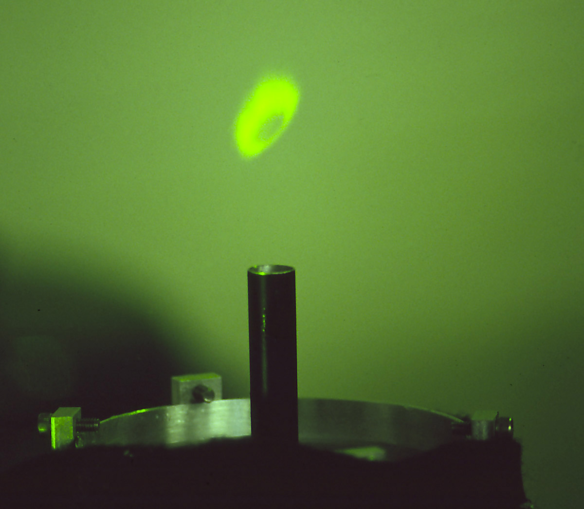
In order to reduce this droplet scatter and make the core of the jet visible, a 4"
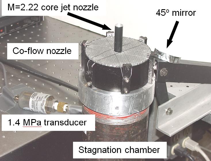
diameter co-flow was created around the main M=2.22, 0.44" diameter jet. The 10 m/s
coflow was created through letting the same compressor air (200 psia, T0=300K, dew
point 233K) feeding the main jet pass through a number of holes in the nozzle base
and then through a ball-filled chamber and several screens to assure reasonable
uniformity. The photo below shows a side view of the entire assembly on top of a
piece of 4" pipe serving as stagnation chamber.
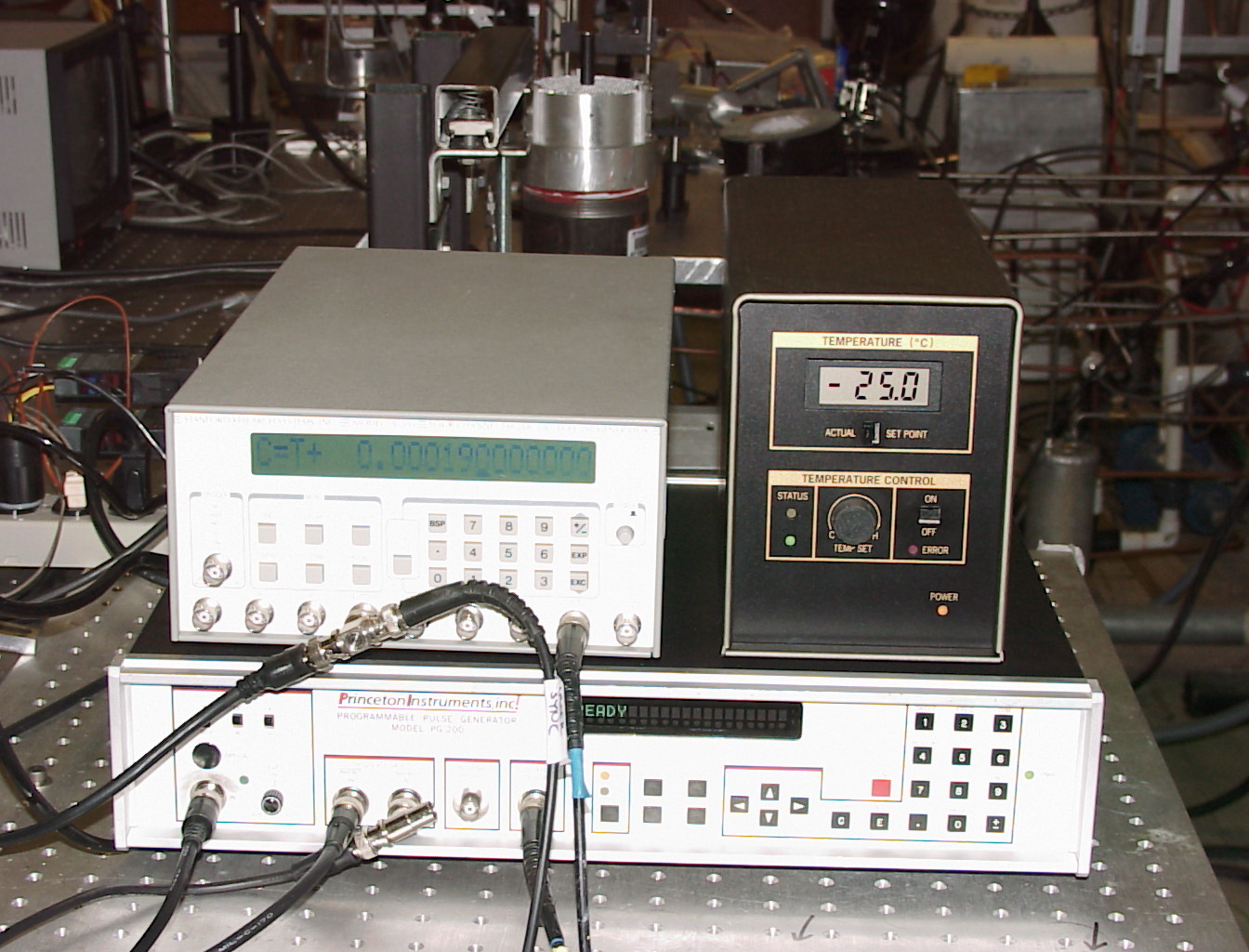
To allow the FRS experiments to be run with ambient lighting on, the gate width
of the cameras were kept at 1 microsecond. During this period of time, the laser
Q-switch was opened, giving a 10 ns long pulse of light that froze any flow features.
The experiment was controlled by a DG535 delay shown in the photo below together with
the Pentamax pulser and power supply/temperature controller.
As a comparison to the FRS results, Pitot probe measurements were carried out using
a square-cut 0.065" OD probe. The probe could also be fitted with a sharp conical tip
with static taps on the surface, allowing the static pressure to be measured at each
point as well.
Results
In addition to the two methods discussed above, velocity data was also available from
Eggers 1966 survey of a 1" diameter M=2.22 free jet. Comparing the three sets of data
as shown below, it can be seen that the agreement is only fair. While the Pitot
measurements may suffer from centerline offset O(0.1D(Pitot)), this is not enough to
explain the differences between the present Pitot data and that of Eggers. The main
reason for this is believed to be that the scaled boundary layer thickness in the 1967
survey was thicker than in the present experiment.
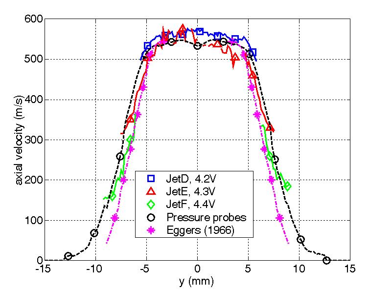
The FRS data acquired at three different laser setpoints show significantly different
velocity (40 m/s) in the shear layer in overlapping regions where two setpoints were
expected to produce data of similar quality. In the uncertainty analysis, several
sources of velocity uncertainty were established. The most significant source was
found to be laser drift (35 m/s), followed by velocity profile broadening due to
turbulence and thermal velocity (12 m/s), image overlap (11 m/s), shot noise
(10 m/s) and whitefield correction error (7 m/s). Note that these are rather
conservative estimates and that the maximum errors typically occur at different
parts of the acquired image. The size of these errors made it clear that in order
to achieve <10 m/s accuracy in velocity measurements, frequent recalibrations of the laser, or better still, monitoring
and adjusting the laser wavelength during the run would be needed along with
a model that can account for the scattered spectrum in a case with significant
seeding in the flow.
Future Work
Currently (June 2008), Jignesh Sutariya is setting up a more advanced FRS experiment where
a feedback system will be used to correct the laser drift and two filtered ICCDs will be used
to determine two velocity components in the flowfield in a high-pressure combustion chamber.
Below are two diagrams of the planned setup.
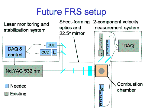

Left: Schematic of 2D FRS setup showing the necessary components to measure two velocity components in the
chamber while maintaining constant laser wavelength.
Right: New high-pressure test chamber with improved 4-way
optical access.
Related publications
You may order the complete dissertation from LuLu as Order # 8513360. An abstract can be found here (pdf).
Links
Back to the UF research page
Older FRS page
Brief literature survey page
FRS page of the Applied Physics Group (Richard Miles, Princeton)
FRS page of Gasdynamics and Laser Diagnostics Research Laboratory (Gregory Elliott, UIUC) (very nice page!)