
Experimental Setup
The high-pressure chamber shown in the figure below is constructed to withstand pressures up to 70 atm and temperatures up to 600 K. The thermocouples and pressure transducers used had an accuracy of +1 K and +10 kPa respectively. For optical access there are three windows in the chamber which provide a field of view that is 22 mm wide and 86 mm long. All experiments were done using a round liquid injector with a diameter D of 2.0 mm and a length-to-diameter ratio of 10. FK-5-1-12 or 'fluoroketone' has been chosen as the injected fluid for its spectroscopic properties and low critical point (Pcr=18.4 atm, Tcr=441 K). Nitrogen has been chosen as the medium into which fluoroketone is injected.

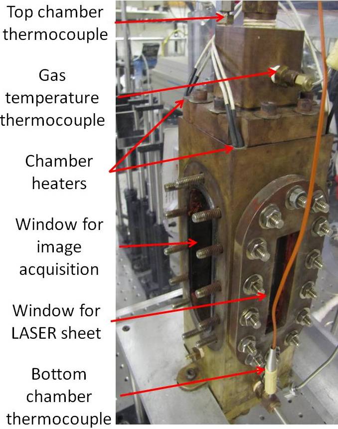
Figure 1: Test chamber schematic (left) and its overall view (right). The liquid and gas injection ports are at the top of the chamber. The chamber can be heated and pressurized to 600 K and 70 atm respectively. Two of the four chamber heaters are shown. The injector diameter is 2 mm.
The third harmonic of Nd:YAG laser was used to excite the fluorescence. Earlier tests have shown that emission spectrum of fluoroketone within 400-500 nm does not reveal significant dependence on pressure and temperature within a range of interest. Based on emission spectra an optical filter with 420 nm centerline and 10 nm FWHM width is placed before the Princeton Instruments Intensified CCD camera lens to eliminate any elastic scattering. The ICCD Camera has a resolution of 1024×1024 pixels, but was cropped to 381×1024 pixels to increase the acquisition rate to 10 Hz and to synchronize it with the laser. The region of interest captured was 14 mm wide and 40 mm long, which corresponds to an axial length-to-jet diameter ratio (x/D) of 20 and a minimum detectable drop diameter of 40 µm. The gate width was fixed at 150 ns in order to capture the entire duration of fluorescence while reducing the background light significantly.
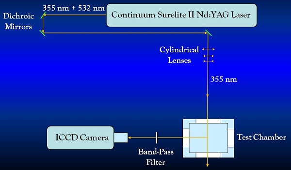
Figure 2: Schematic of the optical diagnostic setup.
A laser sheet of 0.1 mm thickness and 40 mm length as shown in the figure below was focused on the jet centerline to ensure that two-dimensional images were captured accurately. A detailed laser correction method was undertaken to account for the laser intensity loss through the different phases of fluoroketone. This complex calibration has been discussed in detail in an earlier work and has been used in all the current experiments for absorption of the laser sheet through the jet.
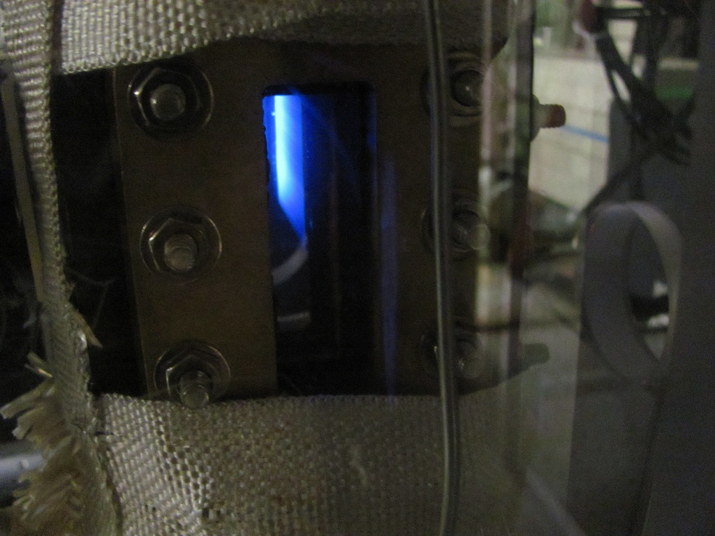
Figure 2: Picture of the laser sheet fluorescence through uniform vapor phase of fluoroketone. The excitation wavelength is 355 nm from the Nd:YAG laser while the fluorescence wavelength is centered around 420 nm.
Experimental Conditions
The experimental conditions are shown in Figure 2 on a reduced pressure (Pr=P/Pcr) and reduced temperature (Tr=T/Tcr) diagram. The goal was to span a range of pressures and temperatures with particular focus around the critical point. Chamber and injectant conditions have been marked separately. Previous studies have shown that supercritical behavior may be encountered even when only one of the parameters, Pr or Tr, is critical. It was observed in this study that both parameters need to exceed the critical values for complete supercritical behavior to exist. Hence, the term 'supercritical' here shall be referred to cases where both temperature and pressure are supercritical, while 'subcritical' shall be referred to cases where only the temperature is subcritical. The highest pressures tested were nearly 2Pr i.e. 37 atm, while the highest temperatures tested were 1.35Tr i.e. 583 K. This was done to ensure that supercritical conditions were achieved even if the mixture effects shifted the critical point.
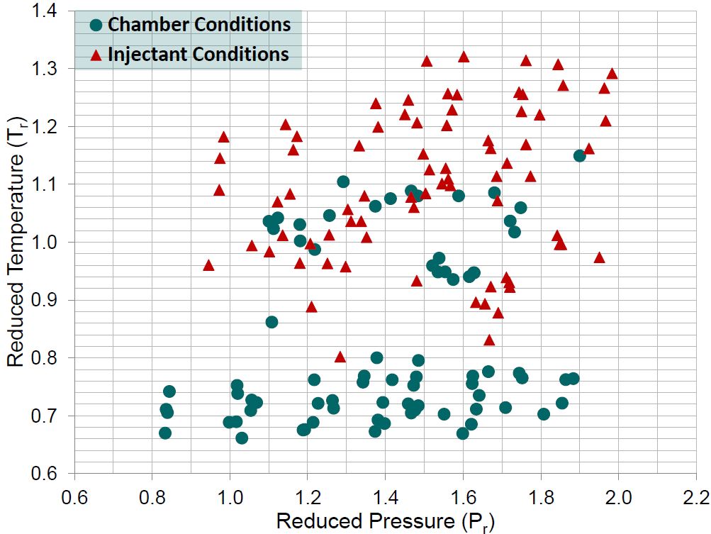
Figure 3: Selection of the experimental conditions. Reduced temperatures and pressures have been selected to cover the subcritical to supercritical regime. The plot indicates both the chamber and the injectant conditions independently.
Selected Test Cases for Supercritical Injection
| Case | Tr,ch | Tr,inj | Pr,ch | Pr,inj | Flow Rate (g/sec) | Uinj (m/sec) |
|---|---|---|---|---|---|---|
| 1 | 0.69 | 1.13 | 1.38 | 1.51 | 19.31 | 20.98 |
| 2 | 0.72 | 1.21 | 1.86 | 1.97 | 18.33 | 17.95 |
| 3 | 0.76 | 1.29 | 1.88 | 1.98 | 17.24 | 20.31 |
| 4 | 0.80 | 1.31 | 1.38 | 1.51 | 16.99 | 30.00 |
| 5 | 1.04 | 1.00 | 1.26 | 1.34 | 17.82 | 7.07 |
| 6 | 1.06 | 1.08 | 1.37 | 1.47 | 16.78 | 14.56 |
| 7 | 1.08 | 1.08 | 1.41 | 1.50 | 17.35 | 14.47 |
| 8 | 1.09 | 1.18 | 1.47 | 1.67 | 18.64 | 20.57 |
Table 1: Selected test conditions for the binary species experiments