 CVS One Time Use Camcorder Hack CVS One Time Use Camcorder Hack
Updated 10-10-05:
Contains OS X
software.
With a soldering iron, a
dremel tool, and some sacrificial USB cable, the $30 CVS one time use digital
camcorder becomes a multi-use digital camera.
The idea for this hack came from articles
circling the internet about a homemade cable that allows you to transfer data from your
"one time use" CVS Digital Camcorder to computer, effectively making it a fully
functional digital camcorder. Well, I decided to take a step further for a
couple of reasons. One, I didn't own or have access to a Palm m100 or Palm III
cable (and no store in town sells the outdated cables) that I could hack apart.
Two, I didn't want to have to lug a butchered cable around with me if I wanted
to connect my camera to my laptop or another computer. So, I decided to add a
USB port to my CVS Cam.For this
project I decided to use a USB type A Female connector in my camera. Although
using a female B connector is probably more practical because it is not only
smaller, but also USB A-A male cables are much harder to find than the A-B
cables that anyone who has a printer owns. In my case, I had an A-A male cable
and an A female port, so the choice was made for me. These directions could be
used for either A or B female
ports.The things you will need for
this project are:Soldering
IronSolderDremel
Tool (or grinding/cutting bits for a power
drill)A USB Cable Extension or USB coupler
with female endA Standard USB A-A (or A-B)
CableSmall
ScrewdriversXacto/Utility
KnifeFirst, remove the battery door,
battery lock, and batteries from the camera. To do this, look at the bottom of
the device. You should see a little slot by the FCC logo. Insert a pin or
something thin into the slot and pull down on the switch inside, then slide off
the battery door.
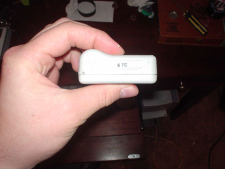 The
battery slot is in the center by the FCC
logo. The
battery slot is in the center by the FCC
logo. 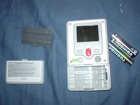 Camera
with batteries removed.Next, we have
to open up the camcorder. The back of the camcorder is held on with 4 small
screws. Two are in the top corners, one is left of the power button and one is
right of the speaker. I used a utility knife to cut out the sticker covering
the screw holes and then undid each screw. The piece should lift off fairly
easily. If not, it's probably just being held up at the bottom by the battery
storage area; gently tap it
apart. Camera
with batteries removed.Next, we have
to open up the camcorder. The back of the camcorder is held on with 4 small
screws. Two are in the top corners, one is left of the power button and one is
right of the speaker. I used a utility knife to cut out the sticker covering
the screw holes and then undid each screw. The piece should lift off fairly
easily. If not, it's probably just being held up at the bottom by the battery
storage area; gently tap it
apart. 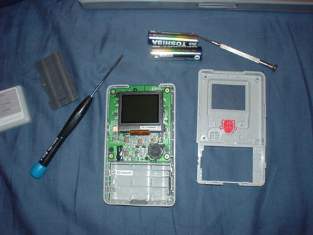 The
camera with back plate removed.Once
the back plate is removed, you must remove two more screws that are holding the
circuit board into place. They are located in black on the above picture just
above where the bottom screws on the back plate would meet the circuit board.
At this point in the construction take your USB extension cable (or whatever
you're using to create the port on your camcorder) and cut it in half and strip
the outer casing so that the red, black, green, and white USB wires are exposed.
Then, test fit the connector and cables into the base of the
camcorder. The
camera with back plate removed.Once
the back plate is removed, you must remove two more screws that are holding the
circuit board into place. They are located in black on the above picture just
above where the bottom screws on the back plate would meet the circuit board.
At this point in the construction take your USB extension cable (or whatever
you're using to create the port on your camcorder) and cut it in half and strip
the outer casing so that the red, black, green, and white USB wires are exposed.
Then, test fit the connector and cables into the base of the
camcorder. 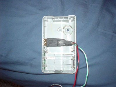 Case
with cable inserted.My cable fit in
perfectly horizontally, but I couldn't sit the circuit board flush on it. So, I
used a utility knife to cut away at the molded plastic until it sat flush in the
casing. The next step was to create a hole in the side of the casing. I marked
the inside of the case with a marker and then cut it open with a Dremel tool and
cleaned up the edges with a utility
knife. Case
with cable inserted.My cable fit in
perfectly horizontally, but I couldn't sit the circuit board flush on it. So, I
used a utility knife to cut away at the molded plastic until it sat flush in the
casing. The next step was to create a hole in the side of the casing. I marked
the inside of the case with a marker and then cut it open with a Dremel tool and
cleaned up the edges with a utility
knife. 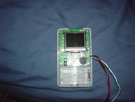 Top
view of the case with USB cable and circuit board flush
mounted. Top
view of the case with USB cable and circuit board flush
mounted. 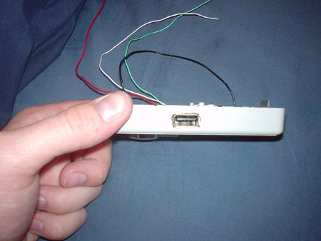 Side
view of the case with USB port hole and flush mounted circuit
board.After test fitting the circuit
board and cables, lift the circuit board back out and look at the top of the
camcorder case. At this point you should create a groove in the top piece of
plastic to let the cables run through. I used the grinding bit of my Dremel to
create a small channel, you could also just cut the soft plastic with a utility
knife. I then applied a piece of 3M tape to hold the cables down and prevent
them from getting in the way of the lens and routed through the channel I just
created. Side
view of the case with USB port hole and flush mounted circuit
board.After test fitting the circuit
board and cables, lift the circuit board back out and look at the top of the
camcorder case. At this point you should create a groove in the top piece of
plastic to let the cables run through. I used the grinding bit of my Dremel to
create a small channel, you could also just cut the soft plastic with a utility
knife. I then applied a piece of 3M tape to hold the cables down and prevent
them from getting in the way of the lens and routed through the channel I just
created. 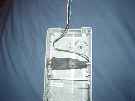 USB
cable properly placed and routed through the new
channel.At this point I positioned the
circuit board above the plastic on a table in a position so that I could just
pivot it back into the case so that I could trim down the USB cable. Make sure
to give yourself a little extra slack that you can stuff back into the case in
the event you screw up. Strip down the ends of the wires and get ready to
solder! Looking at the circuit board notice the J5 printed on it. We'll count
the first pin as 1. On pin 6 tin and solder the red (+5V) wire, on pin 7 tin
and solder the black (ground) wire, on pin 8 tin and solder the green (+) wire,
and on pin 9 tin and solder the white (-)
wire. USB
cable properly placed and routed through the new
channel.At this point I positioned the
circuit board above the plastic on a table in a position so that I could just
pivot it back into the case so that I could trim down the USB cable. Make sure
to give yourself a little extra slack that you can stuff back into the case in
the event you screw up. Strip down the ends of the wires and get ready to
solder! Looking at the circuit board notice the J5 printed on it. We'll count
the first pin as 1. On pin 6 tin and solder the red (+5V) wire, on pin 7 tin
and solder the black (ground) wire, on pin 8 tin and solder the green (+) wire,
and on pin 9 tin and solder the white (-)
wire. 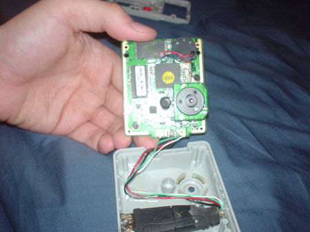 Camcorder
with USB cable soldered on.Now, all we
need to do is reassemble the camcorder and install some drivers. There are many
options for drivers out on the internet. I think the easiest to use is
carpespasm's QuickInstaller. The QuickInstaller installs all of the needed
drivers, the latest version of BillW's Ops, and adds shortcuts to both the
desktop and start menu. As of now I don't know of a Mac version of these
drivers. You can find QuickInstaller at the official repository or I keep
a copy of the latest version I have installed locally. Once the drivers are
installed, double click the Ops shortcut and plug in the camcorder. If done
properly, the camera should be recognized by your computer and you can now
unlock it, take off the movies, and reformat the hard drive using Ops. Ops has
a great read me that explains the basic
process.Update:
I have now found software that will
allow you to download the videos taken from your CVS camera to a Mac. I've
tested it on OS X Version 10.4.2 and it works flawlessly. You can find the
software here. Camcorder
with USB cable soldered on.Now, all we
need to do is reassemble the camcorder and install some drivers. There are many
options for drivers out on the internet. I think the easiest to use is
carpespasm's QuickInstaller. The QuickInstaller installs all of the needed
drivers, the latest version of BillW's Ops, and adds shortcuts to both the
desktop and start menu. As of now I don't know of a Mac version of these
drivers. You can find QuickInstaller at the official repository or I keep
a copy of the latest version I have installed locally. Once the drivers are
installed, double click the Ops shortcut and plug in the camcorder. If done
properly, the camera should be recognized by your computer and you can now
unlock it, take off the movies, and reformat the hard drive using Ops. Ops has
a great read me that explains the basic
process.Update:
I have now found software that will
allow you to download the videos taken from your CVS camera to a Mac. I've
tested it on OS X Version 10.4.2 and it works flawlessly. You can find the
software here. 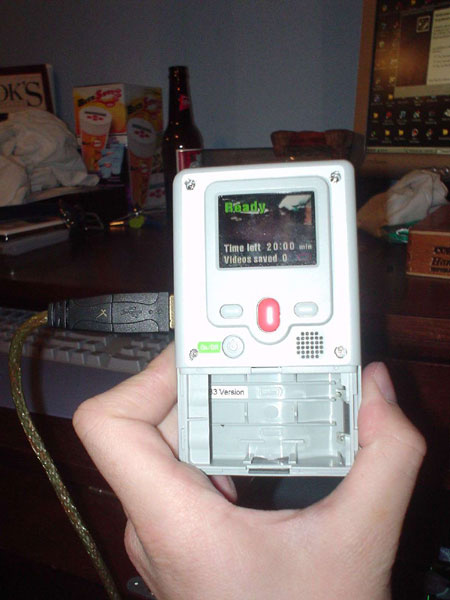 Camcorder
plugged in and powered by USB.Thanks
to the following for pioneering a lot of the work that made this hack
possible:Raymond Kawakami
i-hacked
camerahacksmaushammer Camcorder
plugged in and powered by USB.Thanks
to the following for pioneering a lot of the work that made this hack
possible:Raymond Kawakami
i-hacked
camerahacksmaushammer
Posted: Sat
- September 10, 2005 at 01:49 PM |
|
Quick Links
Calendar
| | Sun | Mon | Tue | Wed | Thu | Fri | Sat
|
Categories
Archives
XML/RSS Feed
Blog Roll
Statistics
Total entries in this blog:
Total entries in this category:
Published On: Mar 21, 2006 02:41 AM
|


