Installation detail of multiple wing control surface actuators
The motivation behind this project is encompassed in the installation of these wing servos. While a mere 16 servos is far from the eventual goal of a fully morphing aircraft, developing effective sensing and control of these actuators could be a large step towards changing the way airplanes are controlled.
The scope of this project, at least in this initial phase, will not see any of the feedback control or adaptive schemes that were originally planned. Rather, emphasize will be strictly on developing a testbed for future control experiments and some initial experiments with innovative control actuation. Once the aircraft and actuators have been properly characterized, control algorithms can be developed and tested using this platform.
The approach to designing this testbed is simple: Replace the two conventional, full-length, strip ailerons with 16 smaller surface. The total surface area will be the same, only the multiple actuators will allow the aileron to be highly configurable. Because the individual surfaces are relatively small, micro servos can be used to actuate them, without sacrificing control speed or authority. These servos are lightweight and small enough to imbed in the wing surface without critically disturbing the airflow.
The actuators are controlled by the pilot using the aileron command. The initial control scheme is simply a scaling of this command. e.g. the actuator command signals are scaled progressively such that the outboard surface is deflected fully and the inboard surface is only deflected 12.5% of the command. This progressive deflection is likened to the Wright brother's "wing-twist" method of roll control. It has potential aerodynamic and structural advantages such as increased roll rate and a gradual, more distributed loading on the wing.
To date, the actuators on the left wing panel have been installed and tested. Detail of the installation procedure follows:
|
|
|
|
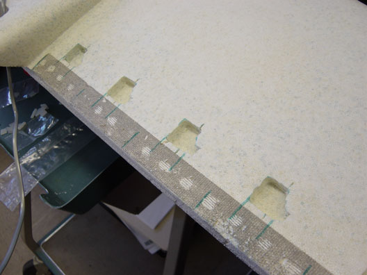
Figure 1: Servo cavities in right wing |
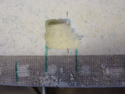
Figure 2: Cavity detail |
Figure 1 shows the cavities for the servos in the upper wing
surface. These were made using an outline of the servo and a Dremel tool with the
steel cutting bit. When installed, the servo sits flush with the wing surface,
minimizing the aerodynamic protrusions. The servos are spaced 3.5"
apart and actuate in the center of each surface. The eight surfaces take
up the entire half-span of the wing. The cavities are cut 2" forward
to the trailing edge to give sufficient clearance for the hinge and control
linkage.
Figure 2 details a close-up of the Dremeled cavity. Rather than
cutting off the mounting lips, I've cut the foam to let the plastic slide in.
This, I imagine, will help resist torque from the surface loading. It's
surprisingly easy to get a clean cut with the bit. Even the bottom surface is
nice and smooth.
 |
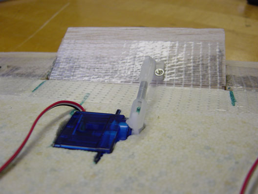 |
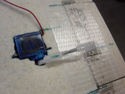
| Figure 3: Installed actuator | Figure 4: Surface deflection |
Figures 3 & 4 show the installed actuator, control linkage, and hinged control surface. Standard R/C accessories, namely nylon clevises, threaded pushrod, and nylon control horn are used to form the control linkage. The threaded rod is useful for tweaking the surface angle to adjust to slight discrepancies between the individual servos. The tape used for hinging is called 3M Extreme Application tape. Bi-directional fibers running through the tape help keep the tape together throughout high-G maneuvers.
 |
|
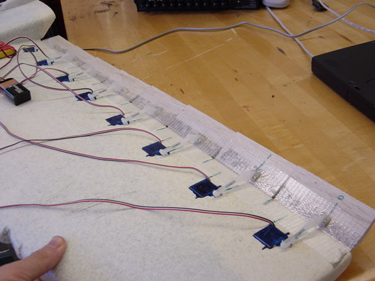
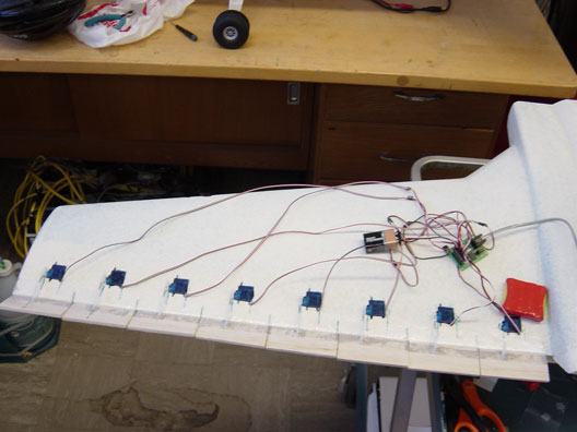
| Figure 5: Top view of left wing panel | Figure 6: Front-quarter |
Figures 5 & 6 show the completed actuator array. The wires will be later contained in a milled channel just forward of the TE. The different lengths of the servo leads minimize wire clutter inside the fuselage. Figure 6 illustrates the progressive control scheme on the bench. It remains to be seen whether there is any merit to it in flight.
The servos are plugged into a servo controller which commands servo position based on a serial interface. More detail on this device appears below. The red object is the battery which is needed as an external power source for the servos.
|
|
|
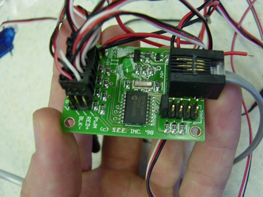
Figure 7: Serial servo controller by Scott Edwards Electronics - very cool |
Figure 7 shows the serial servo
controller that will do the brunt of the work managing the actuators. Quite the amazing little board,
it's perfect for aerospace engineers with some electronic aspirations. For
the flying setup, two of these boards will be daisy-chained to control 16 total
servos. The boards generate a PWM signal to each servo based on serial
input. By sending three command bytes to it, the servos each servo can be
controlled individually at 15Hz - an acceptable rate for flight control.
On-board, the bytes will be sent from a microcontroller that is connected to the
aileron channel on the R/C receiver. The microcontroller, an Atmel
AVR90S8515 will read the aileron position commanded by the pilot then perform
all the mathematical scaling for each servo. The byte values are then
computed and sent to the servo controllers
|
|
|
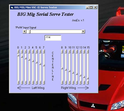
Figure 8: Big Mig serial servo test program |
Figure 8 shows a screenshot of the Visual Basic program that I made to test the control
of the
servos. The horizontal scroll bar at the top is representative of the input
signal from the receiver's aileron channel. Based on this, all 16 "servos" or
vertical scroll bars are scaled. In addition to the visualization, the program
outputs serial bytes to the servo controller to move each servo to the scroll
bar's position. This is identical to the progressive actuation that will be
implemented for the first operation mode.
|
|
|
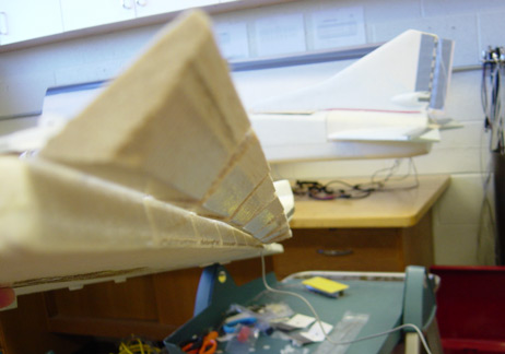
Figure 9: Wing-tip view of progressive actuation |
At last... progressive control :-) Figure 9 shows the fruits of my labor. The end view clearly illustrates the relative position of the control surfaces. Will this do anything apart from looking pretty on the ground? Who knows, but we'll soon find out. The Mig-27 fuselage sits patiently in the background. Oh to be flying right now...