Page Links:
RE:vision 1 RE:Vision 2 RE:Vision 3 RE:Vision 4 Steering Wheel Display
Project Description:
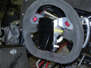
SparkyTRAC centers around an ATMEL 8-bit RISC microcontroller with a system speed of 8MHz. Four discrete wheel speeds are measured via Hall type sensors and a ferrous sensor ring. A digital LED display is mounted in the center of the steering wheel. It displays percent slip and system state. A button is also mounted on the steering wheel to temporarily disengage the traction control to allow for throttle steering.
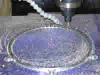
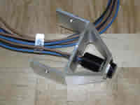
[left] Billet CNC Sensor Ring [right] Hall Wheel Speed Sensor
Wheel speeds are checked at 1mS intervals. Front to back, left to right pairs are compared. If excessive wheel spin is determined, SparkyTRAC directly cuts the +12V connection to all injectors for a period of at least 100mS via high current, high speed (~200nS switch time) TTL gate driven FET.
The software employs both an "On Clamp" and an "Off Clamp" to ensure a smooth transitions between on and off states. Moreover, there must be traction control requests greater than either clamp value to change states. Typically, the "On Clamp" value is twice that of the "Off Clamp."
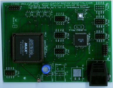
SparkyTRAC's first incarnation employed the ATMEL ATMega128 and an Altera EPM7128SLC84-15 CPLD. There were two discrete power supplies, one for sensors and another for controllers/logic (not mounted in picture). Originally, the CPLD held 4 discrete wheel speed counters triggered by the rising edge of the wheel speed sensors. These 8-bit count values were directly sent to individual ports on the ATMega128 via 32 bit bus. Optoisolators electrically isolated the system form the wheel speed sensors to reduce system noise. The footprint for the FET is seen next to the connector JP1_9 in the lower right.
Version 2 reduced the number of bus lines between CPLD and microcontroller. By implementing an 8:1 multiplexer in the CPLD, bus lines were reduced to 11. RE:vision 2 also added support for both the disable button and the display. On the reverse side lies a single 5A, 5V regulator. All capacitors and resistors are surface mount. A significant size reduction occurred between R1 and R2. Lastly, a bridge rectifier was added as a safety measure.
Versions 2 and 3 both interacted with the MoTeC ECU to apply engine cut. Effectively, they are simply slip sensors. When slip occurred, SparkyTRAC applies ground to an ECU input where the ECU then handled engine cut. The FET was deleted as it was unnecessary.
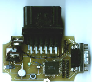
Major changes in this latest version included deletion of the CPLD and reintroduction of a second voltage regulator that was lost in R2. Wheel speeds are directly counted by the Atmel through external interrupt controlled counters. The second voltage regulator provided power regulation to the display. This piece was added by hand drilling through the PCB and connected with small gauge wire. Additional debounce circuitry (on back) was added for display control and traction disable.
The large black AMP Econoseal connector replaced the smaller Hirose connector (see left side of R2 picture). This allowed for an easy swap between SparkyTRAC and the MoTeC TC Mux (MoTeC's proprietary traction control multiplexer).
The latest version permanently adds regulator #2 and switches the regulator footprint form a surface mount TO-263 to TO-220. This allows for larger heatsinks as these are vertically placed. Also, the high speed FET was reintroduced. SparkyTRAC once again directly controlled injector cut to free up ECU inputs.
The display uses eight four character alpha numeric LED displays. ASCII values are written directly to the IC's from an ATMEL ATMega8. Power regulation is provided by SparkyTRAC.