Ferrarobot
Kyle L. Carithers
Intelligent
Machines Design Lab
Spring
2006

Mechanical
devices
The typical setup used in constructing most robots in
this class includes two wheels with a motor attached to each, “TJ”
style, or differential drive. The
two wheels both power and steer.
The robot turns by applying a greater voltage to one motor or the
other. This system does have some
drawbacks.
The main drawback to this system is that two motors
will supply at least slightly different power. A robot in this setup will experience
difficulty driving straight. In most
cases, the robot will have to use a third roller or swivel wheel. The size of the robot is limited in this
setup because of the torque required to overcome the friction involved.
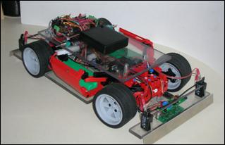
For Ferrarobot, I chose to build the robot to
simulate car-like driving. This
involves rack and pinion steering and rear wheel drive powered by a single
motor. The benefit of this setup is
that the robot should have little problem traveling straight. There is a single motor that applies an
even amount of torque to each wheel.
A larger robot can be constructed that does not require a high friction
third wheel. The rear wheels can
focus on driving while the front wheels can focus on steering.
One of the major disadvantages of this system is
that steering becomes much more complicated. The front steering wheels now have to
rotate together. The complicated
mechanical aspect of this type of steering is a major reason for why I chose to
incorporate Lego products into my design.
Another disadvantage is that with this setup, the robot has a turning
radius. In the two wheel setup, if
the robot must go to a specific object forward and to the left, the robot can
stop, turn towards the point, and then move in a generally straight
direction. In the front wheel drive
setup, it must go forward and left at the same time. Programming the robot becomes more difficult
as it must account for this turning radius.

Steering
Column
I built the rack and pinion steering system from
Lego pieces in such a way that it could be bolted directly to the polycarbonate
platform eliminating the need for any type of connecting piece. A Lego shaft connects the servo to the
pinion gear. The pinion gear meshes with the rack gear. When the servo rotates, the pinion
rotates and the rotation is converted into translation of the rack. The rack is
connected to each wheel hub by a rod. Each hub is mounted by a ball and socket
joint and rotates with translation of the rack.
Pinion Gear
Rack Gear


 Differential Gear
Using a single motor has clear benefits. In most cases though, using one motor
requires using a single, connected axle.
A problem arises when wheels must rotate at different speeds, which
would occur any time the robot is turning.
A single axle of course does not allow for wheels at each end to rotate
at different speeds. If a turn is
attempted, then slip must occur, meaning a tire would slide against the road or
other surface. When dealing with
larger robots or vehicles, more weight and friction is involved. This makes slipping harder because it
requires a greater force and makes turning much more difficult because turning
in this case requires slipping in the rear wheels.
To allow each wheel to rotate at a different spend,
avoid slipping, and improving the ease of turning a differential is used. The differential applies an equal amount
of torque to each wheel but allows for the wheels to rotate at different
speeds. The best way to explain how
this is done is by showing the system under various conditions.
 In this picture, from Wikipedia,
both wheels would be turning.
Assuming that a motor applies torque to the blue gear and that the red
and yellow gears rotate at the same velocity, the green gear would apply an
equal torque to both the red and yellow gears. This could occur when the robot is
traveling either forwards or backwards.
In this picture, from Wikipedia,
both wheels would be turning.
Assuming that a motor applies torque to the blue gear and that the red
and yellow gears rotate at the same velocity, the green gear would apply an
equal torque to both the red and yellow gears. This could occur when the robot is
traveling either forwards or backwards.
 In this picture, also from
Wikipedia, the wheel attached to the yellow gear would be turning. Assuming that a motor applies torque to the
blue gear and that the red and yellow gears rotate at the same velocity, the
green gear would apply an equal torque to both the red and yellow gears. This could occur when the robot is
turning, although there would likely be some rotation of the red gear.
In this picture, also from
Wikipedia, the wheel attached to the yellow gear would be turning. Assuming that a motor applies torque to the
blue gear and that the red and yellow gears rotate at the same velocity, the
green gear would apply an equal torque to both the red and yellow gears. This could occur when the robot is
turning, although there would likely be some rotation of the red gear.