
This is a brief description of experiments carried out by Dr Corin Segal, Jonas Gustavsson and Saurav Pathak on a catalytic combustor 2005. In addition to the work in our lab which is focused on gas sampling (mass spectrometry) experimental work is also carried out on a similar setup in Dr Hahn's laser-based diagnostics lab and Dr Mikolaitis is running simulations to study the catalysis process.
The test setup is modelling a small part of a catalytic combustor for a stationary gas turbine fuelled by syngas mixtures. The purpose of the catalyst is to establish low-temperature combustion in a very fuel-riuch mixture, which after incomplete combustion is mixed with excess air and combusted further, allowing low emissions of CO, hydrocarbons and NOx to be achieved simultaneously, thus combining the desirable features of lean and rich combustion. The test setup consists of a steel tube coated with catalyst on the outside which is enclosed in a larger coaxial tube fitted with thermocouples, gas sample ports and windows for observation. In the annular space between the two tubes a rich air-fuel mixture is flowed while the center of the catalyst tube carries cooling air, which downstream of the catalyst is allowed to mix with the rich catalyst exhaust. Since only the catalyst part of the combustor is studied in this setup, the exhaust is then further diluted with excess air to achieve a non-flammable mixture which is exhausted. Figure 1 shows an photograph of the setup, showing the insulated testsection and a pair of electric heaters upstream of the combustor which allow the mixing and cooling airto be independently heated to specified temperatures. The mass flows of the two incoming air streams as well as those of the constituent gases of the syngas (CO, CO2, H2 and CH4) were controlled by mass flow controlers, allowing full flexibility in the gas composition tested.
Figure 1. Overview of experimental setup. Figure 2 shows a closeup of the catalyst section with two windows on one side of the tube for optical access and visual inspection and gas sample ports for mass spectrometry on the opposite side.

Figure 2. Close up top view of catalytic combustor.
Figure 3 shows the catalyst tube glowing hot from heterogenous combustion as a rich, pre-heated mixture of methane and air flows over it.
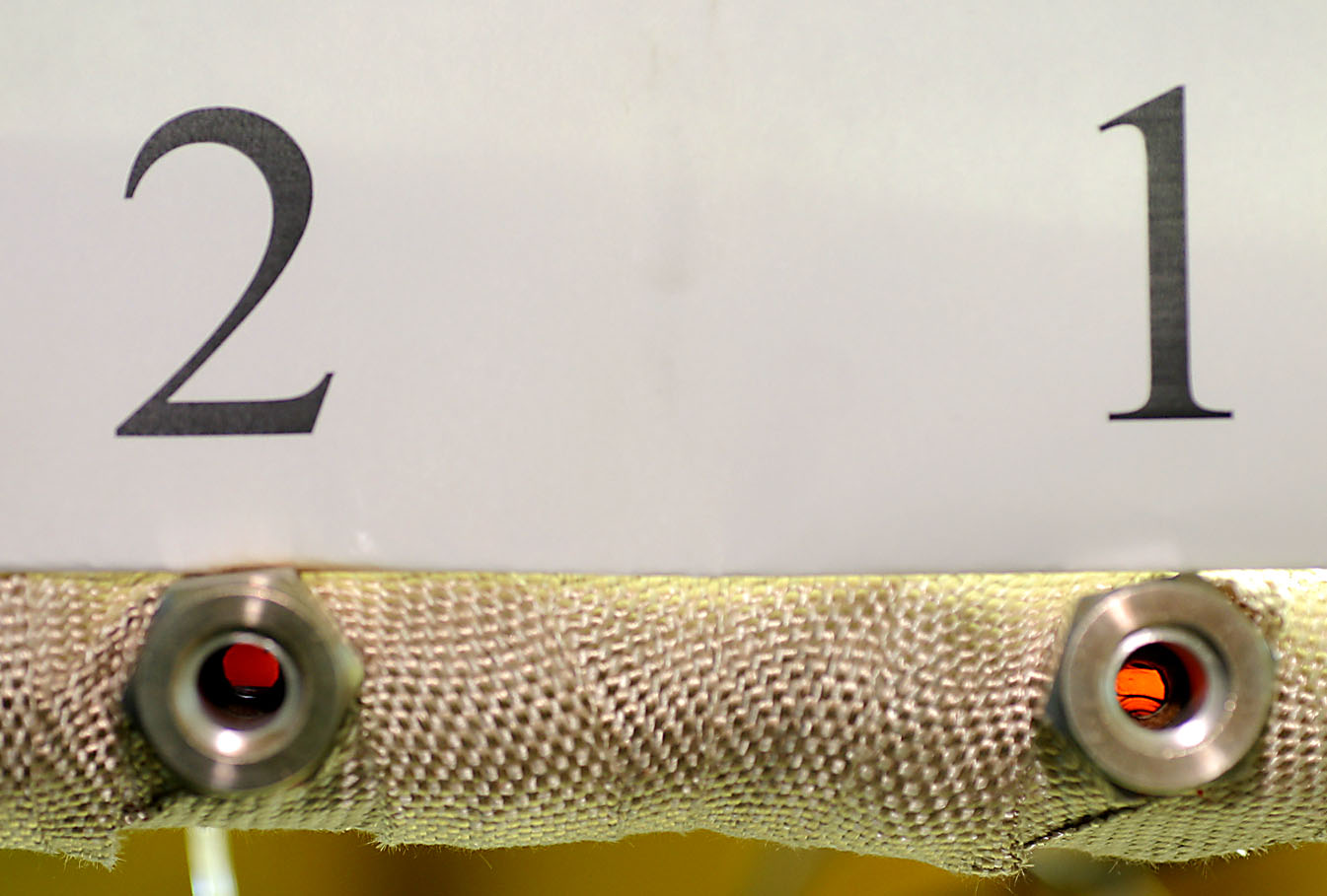
Figure 3. Dual window view during methane combustion - flow from right to left.
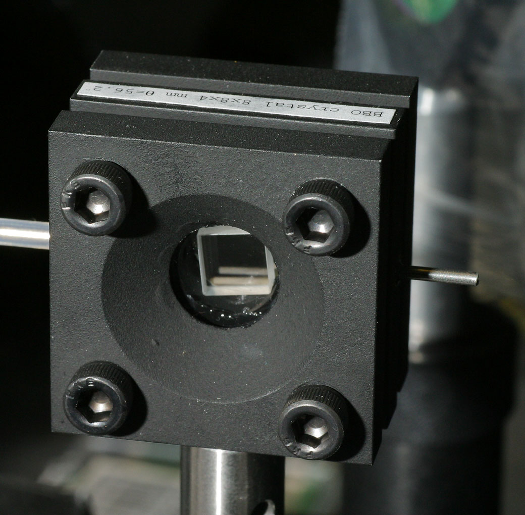
Figure 4. A BBO (Beta-Barium Borate) crystal in its nitrogen-purged housing.
Back to the UF research page
Combustion lab homepage